So you want to add PS4 functionality to your arcade stick? Well too bad. Just wait until there is a third party pcb that is cheap and easy to wire up. Maybe we'll get lucky and there will be a firmware update to any of the
custom ps3 pcb's that are out in the market. Oh, you don't want to wait? You really want it now? Well the only option right now is to padhack a Dual Shock 4 controller. Luckily for us the pcb is common ground. Unluckily for us
the pcb is a pain in the ass to wire up and is quite unforgiving if you mess up. You thought the Xbox One pad hack was hard? This pad hack shits all over it. You accidentally burn off or rip off a contact pad on the ds4 and
you've just wasted $60. The only option after that is to find a via that traces to the contact pad that you've just destroyed. They are not easy to find nor solder to.
So if you think you have the skills or are looking for a challenge you have been warned. Don't hold me responsible if you damage your DS4.
With that being said, let the padhack begin! We will start out with preparing the ds4 pcb.
To begin opening up the DS4 you must unscrew the four screws on the back of the pad.
![IMG_0336_zps442ab332.jpg]()
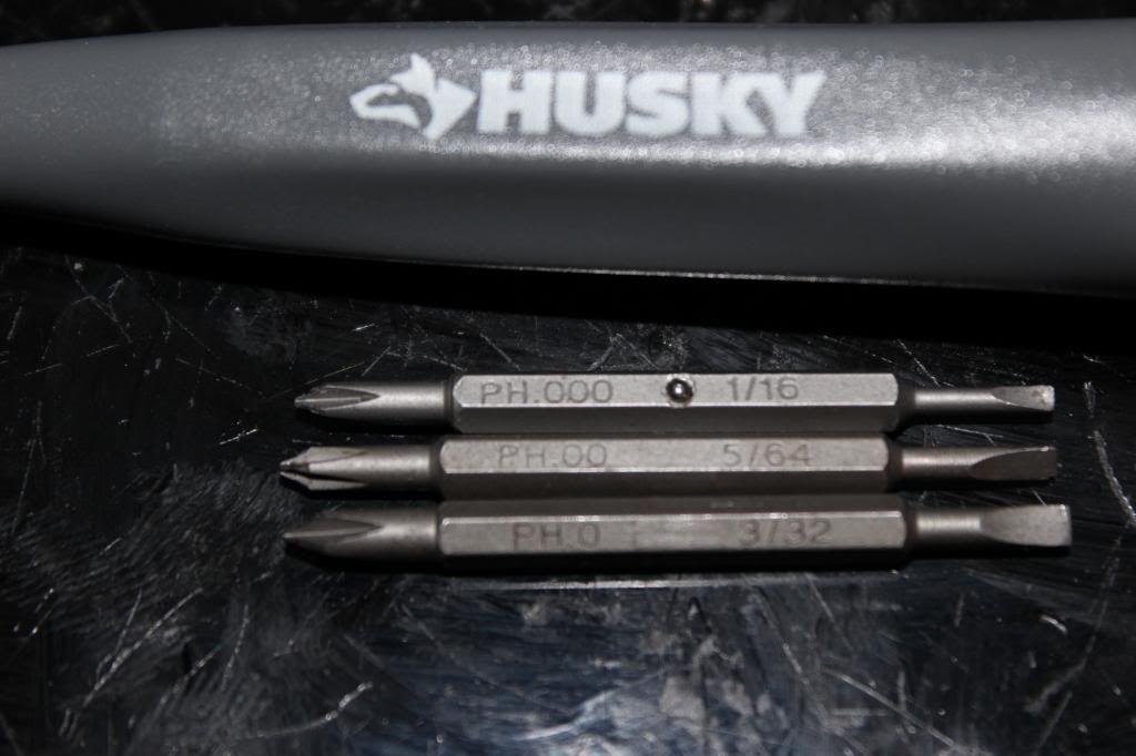
You'll need to use a size #0, #00, or #000 Phillips head screwdriver. If you don't own one then I suggest buying a Husky precision screwdriver set.
![IMG_0337_zps65fe8af9.jpg]()
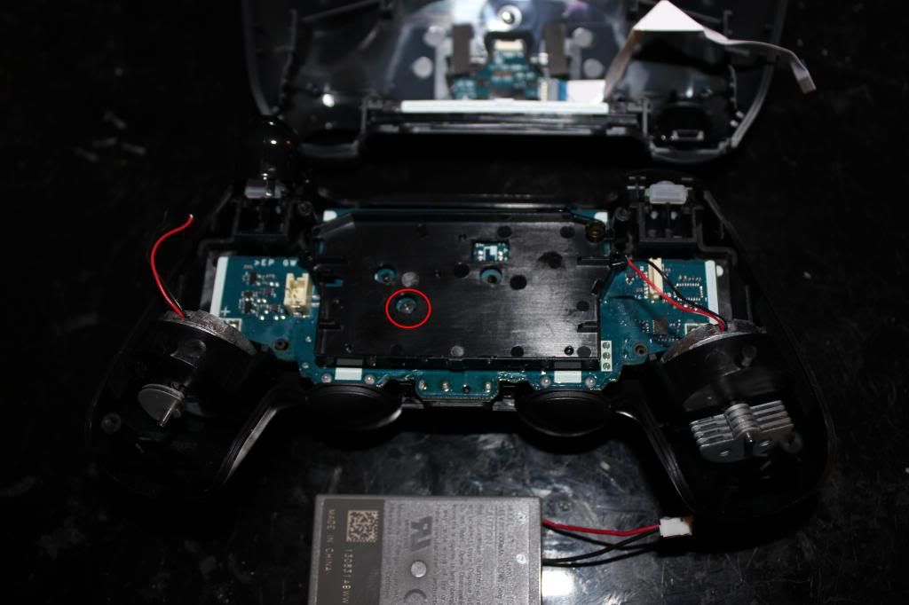
You'll need to use a little force to pull apart the shell, but don't pull the shells too far apart too fast. There is a ribbon cable connecting the usb jack to the ds4 pcb. Pull the ribbon cable out first. Then unplug the
lithium ion battery pack. Then cut off the rumble motor wires.
![IMG_0338_zps823d7882.jpg]()
Circled is one more screw that holds the pcb to the shell.
![IMG_0339_zpsced0a56e.jpg]()
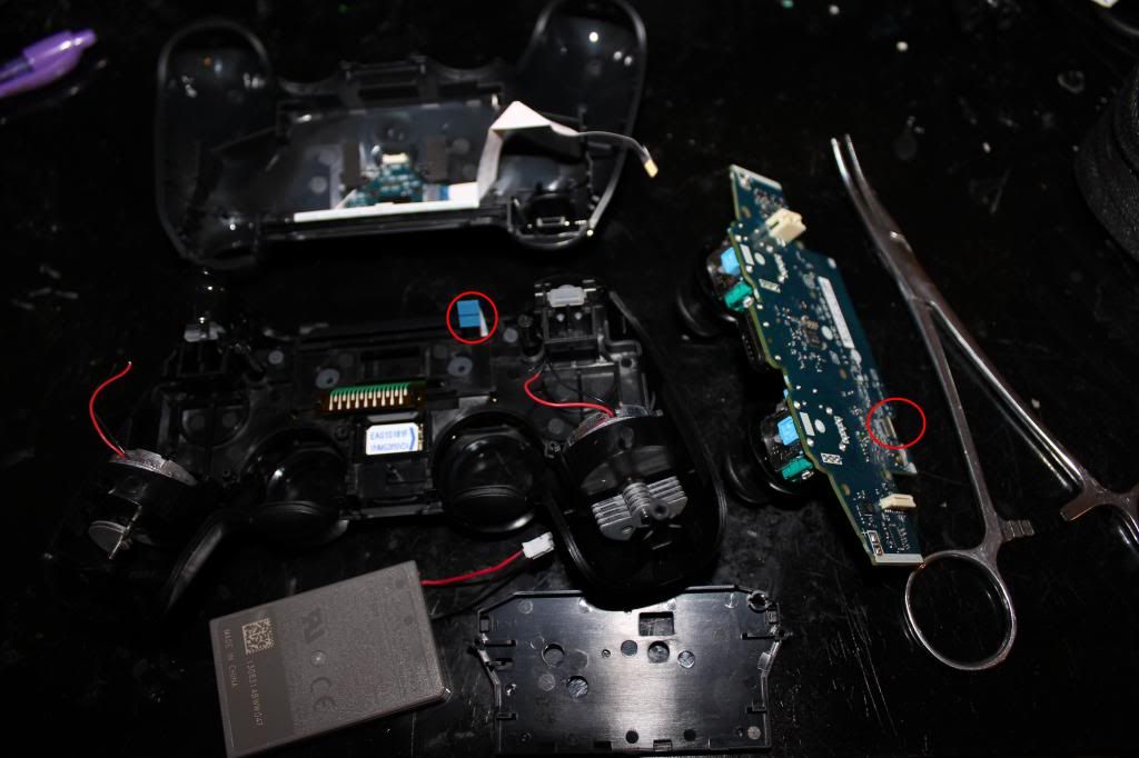
Be careful as you lift the pcb out. There is still one more ribbon cable left that needs to be unplugged. It might be a bit difficult to unplug with your finger so using tweezers or forceps will make things easier.
![IMG_0340_zpsde1f7a4d.jpg]()
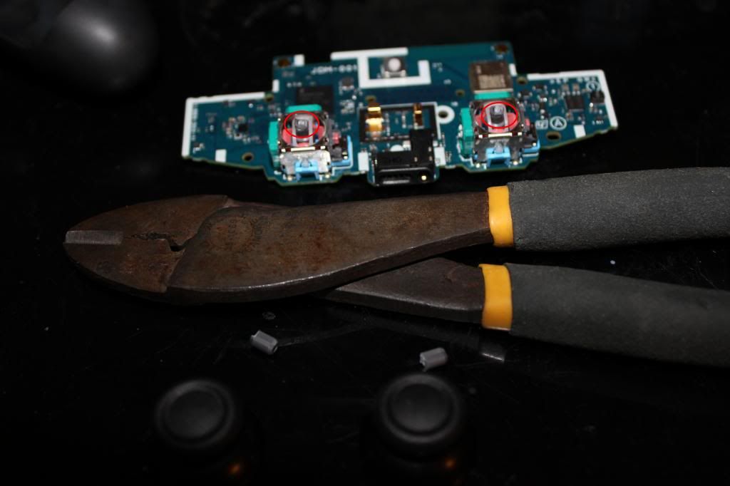
If you have very tight space limitations inside your case you'll probably will want to desolder the analog jacks and neutralize the axis with 10k ohm resistors. However, for most applications just cutting the stubs and gluing
the stick in place will suffice.
![IMG_0341_zpsb1f0d7c5.jpg]()
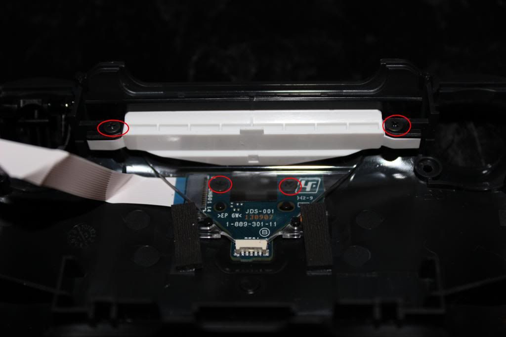
If you want to use the micro usb jack, and I suggest you do, then you'll need to unscrew four screws that hold it in place. The top two have to be removed first. Then the led light thingy can be removed to gain access to the
bottom two screws.
![IMG_0342_zps8f1dea6e.jpg]()
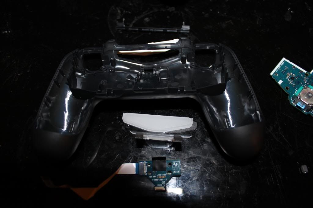
Remove and set aside the micro usb jack.
![IMG_0343_zpsf0d6dec8.jpg]()
This is where you'll be wiring up the joystick and buttons to. Looks fun doesn't it?
![IMG_0345_zps3e268abe.jpg]()
To gain access to the copper contact pads the carbon residue has to be scraped off.
![IMG_0346_zpse7c0faea.jpg]()
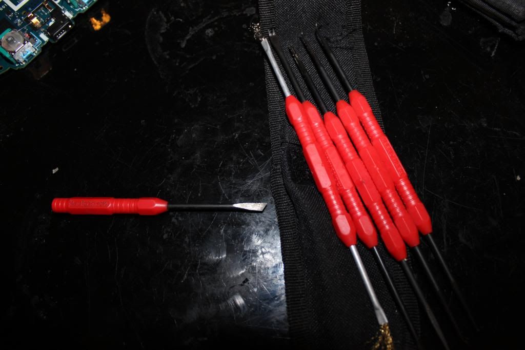
I have a pick set that I got from radio shack that I use to scrape off the carbon pads. The one on the left I accidentally broke in half from trying to pry something off. I suggest not using these picks to pry stuff off.
![IMG_0348_zpsb592d658.jpg]()
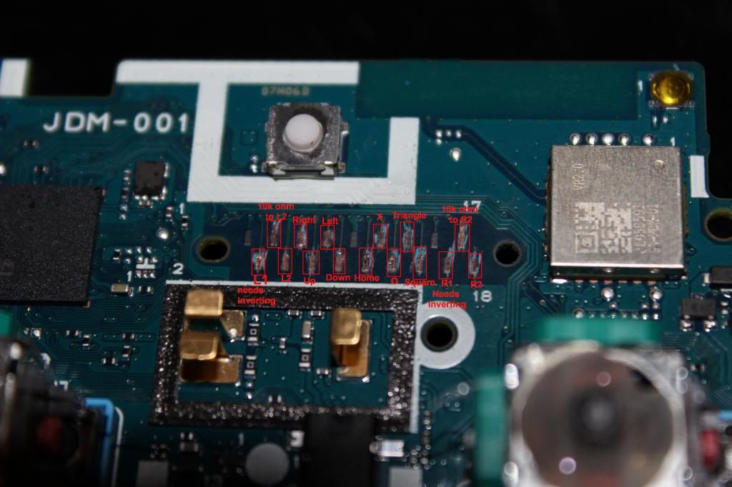
Here's the pinout for the 18 contact pads and which need to be scraped. It is the same for all the model revisions 001, 011, and 020.
1-(Don't worry about me)
2-L1 (needs inverting)
3-10k ohm to pad4
4-L2
5-right
6-up
7-left
8-down
9-ground (Don't worry about scraping me either)
10-home
11-x
12-circle
13-triangle
14-square
15-(Don't worry about me too)
16-R1 (needs inverting)
17-10k ohm to pad18
18-R2
![IMG_0349_zps2f5337b0.jpg]()
Tin the contact pads. Use flux as necessary.
![IMG_0350_zps46ac45f6.jpg]()
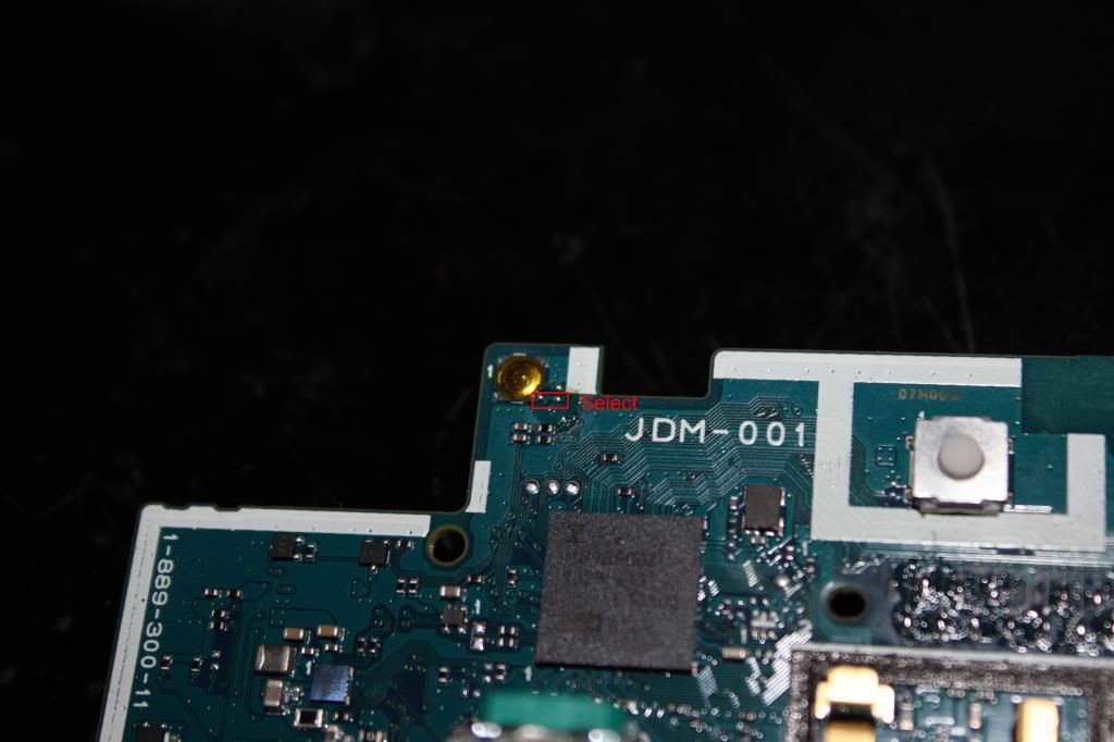
Tin the two very small contact spots in the rectangle for Select.
![IMG_0351_zps5e8432e9.jpg]()
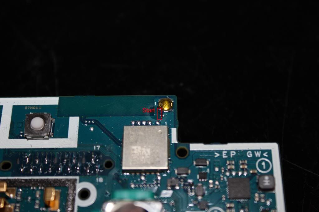
Tin the two very small contact spots in the rectangle for Start.
![IMG_0352_zps4cd67d9f.jpg]()
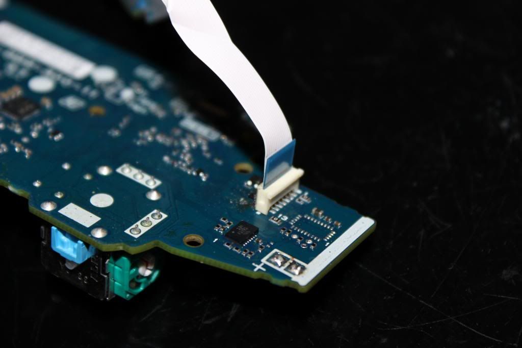
Look at this. This is the ribbon connector for the usb jack. See how simple this is? Want to see how hard your life will be if you don't use this? Just check out the next picture.
![IMG_0354_zps133a474f.jpg]()
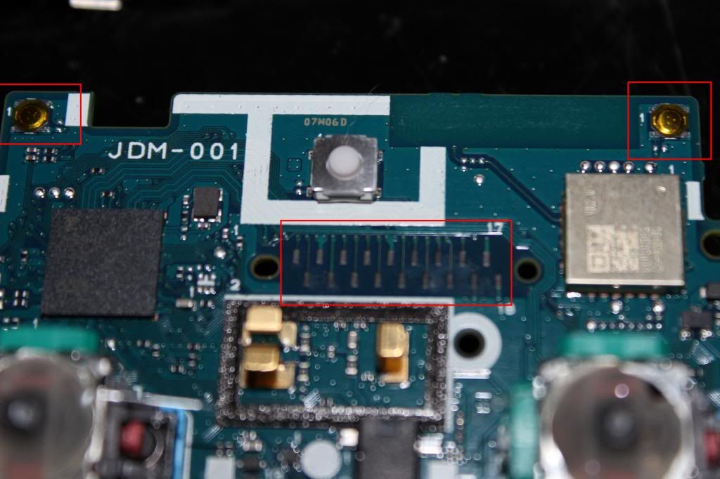
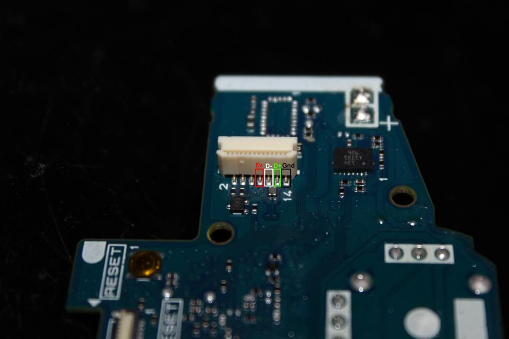
These are the four pins you will have to solder to if you don't want to use the micro usb jack. Pretty small and cramped there.
Note this pin out is for the JDM-001 model and the pictures will reference to that model.
8- Vcc
10- D-
12- D+
14- GND
Pin out for the 011 and 020:
7- Vcc
8- Vcc
9- Gnd
10- D-
11- D+
12- Gnd
![IMG_0353_zpsdb05b9bc.jpg]()
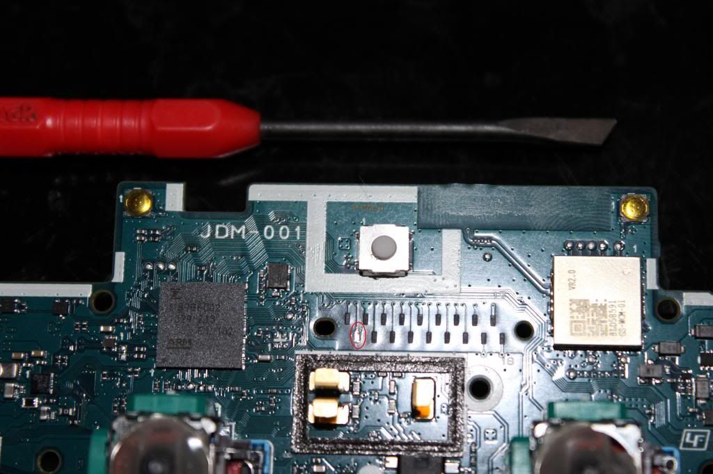
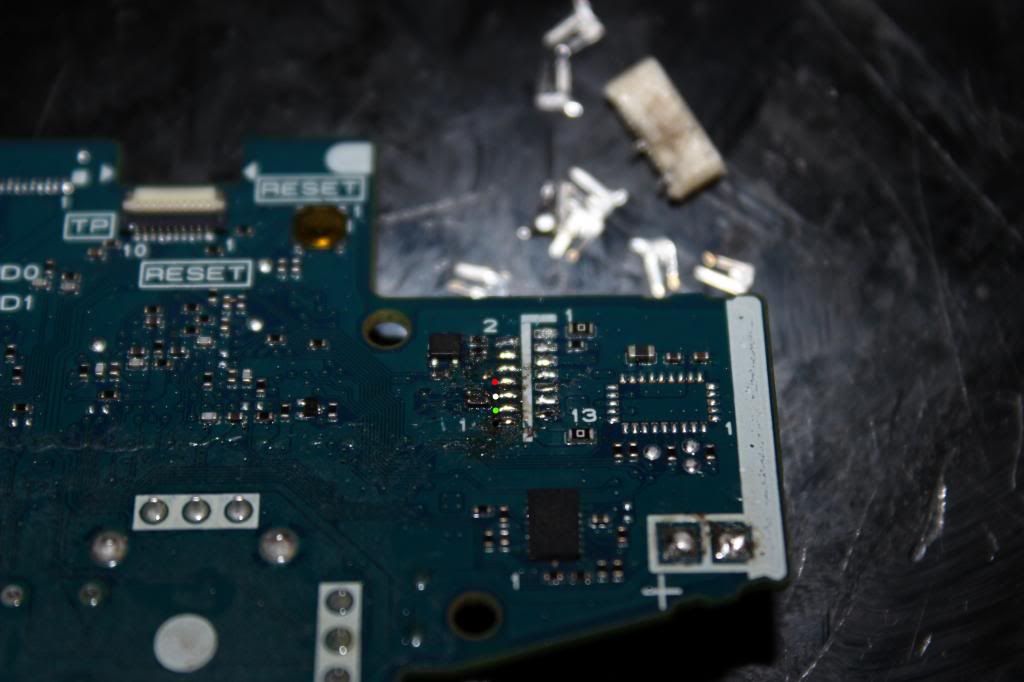
Of coarse removing the ribbon connector will make soldering to the contact pads much easier. This route might be necessary if you are limited in case space. In which case you'd have to remove the battery jack too.
![IMG_0355_zps79565b7c.jpg]()
Now the DS4 pcb is all prepared to begin the wiring!
custom ps3 pcb's that are out in the market. Oh, you don't want to wait? You really want it now? Well the only option right now is to padhack a Dual Shock 4 controller. Luckily for us the pcb is common ground. Unluckily for us
the pcb is a pain in the ass to wire up and is quite unforgiving if you mess up. You thought the Xbox One pad hack was hard? This pad hack shits all over it. You accidentally burn off or rip off a contact pad on the ds4 and
you've just wasted $60. The only option after that is to find a via that traces to the contact pad that you've just destroyed. They are not easy to find nor solder to.
So if you think you have the skills or are looking for a challenge you have been warned. Don't hold me responsible if you damage your DS4.
With that being said, let the padhack begin! We will start out with preparing the ds4 pcb.
To begin opening up the DS4 you must unscrew the four screws on the back of the pad.

You'll need to use a size #0, #00, or #000 Phillips head screwdriver. If you don't own one then I suggest buying a Husky precision screwdriver set.
You'll need to use a little force to pull apart the shell, but don't pull the shells too far apart too fast. There is a ribbon cable connecting the usb jack to the ds4 pcb. Pull the ribbon cable out first. Then unplug the
lithium ion battery pack. Then cut off the rumble motor wires.

Circled is one more screw that holds the pcb to the shell.
Be careful as you lift the pcb out. There is still one more ribbon cable left that needs to be unplugged. It might be a bit difficult to unplug with your finger so using tweezers or forceps will make things easier.
If you have very tight space limitations inside your case you'll probably will want to desolder the analog jacks and neutralize the axis with 10k ohm resistors. However, for most applications just cutting the stubs and gluing
the stick in place will suffice.
If you want to use the micro usb jack, and I suggest you do, then you'll need to unscrew four screws that hold it in place. The top two have to be removed first. Then the led light thingy can be removed to gain access to the
bottom two screws.
Remove and set aside the micro usb jack.
This is where you'll be wiring up the joystick and buttons to. Looks fun doesn't it?
To gain access to the copper contact pads the carbon residue has to be scraped off.
I have a pick set that I got from radio shack that I use to scrape off the carbon pads. The one on the left I accidentally broke in half from trying to pry something off. I suggest not using these picks to pry stuff off.
Here's the pinout for the 18 contact pads and which need to be scraped. It is the same for all the model revisions 001, 011, and 020.
1-(Don't worry about me)
2-L1 (needs inverting)
3-10k ohm to pad4
4-L2
5-right
6-up
7-left
8-down
9-ground (Don't worry about scraping me either)
10-home
11-x
12-circle
13-triangle
14-square
15-(Don't worry about me too)
16-R1 (needs inverting)
17-10k ohm to pad18
18-R2
Tin the contact pads. Use flux as necessary.

Tin the two very small contact spots in the rectangle for Select.
Tin the two very small contact spots in the rectangle for Start.
Look at this. This is the ribbon connector for the usb jack. See how simple this is? Want to see how hard your life will be if you don't use this? Just check out the next picture.
These are the four pins you will have to solder to if you don't want to use the micro usb jack. Pretty small and cramped there.
Note this pin out is for the JDM-001 model and the pictures will reference to that model.
8- Vcc
10- D-
12- D+
14- GND
Pin out for the 011 and 020:
7- Vcc
8- Vcc
9- Gnd
10- D-
11- D+
12- Gnd
Of coarse removing the ribbon connector will make soldering to the contact pads much easier. This route might be necessary if you are limited in case space. In which case you'd have to remove the battery jack too.
Now the DS4 pcb is all prepared to begin the wiring!