Thank you for the update AJtheMishima
Since alot of the pics are down and so many people are asking the same question. I decided to post up pics from my mod i did a couple of days ago. A Lot of the info is on this one post, so hope this helps you guys out.
(These are the tools and materials i used, you can use different sizes or whatever is available to you)
Materials-
JLF-TP-8T(with harness)
OBSF-30 buttons
OBSF-24 buttons
Sanwa 30mm Hole plugs
.187 quick disconnects
22 gauge strand wire
Solder(rosin core)
Tools-
Solder Iron
Solder Sucker
Solder wick
Wire stripper
Wire Crimper
Drill
7/64 drill bit
9/32 socket w/extension
glue gun
Grinder/Dremel/File(whichever one is available)
Pliers/cutters
This is what your starting with.
Using a Phillips head screw driver take the 8 screws out. Using the socket take the nuts off that are holding the top plate on.
![DSC01736.jpg]()
![DSC01737.jpg]()
![DSC01738.jpg]()
This is what it looks like once you open it up
![DSC01739.jpg]()
Next you want you take the 4 screws out that are holding the Hori stick onto the mounting bracket. Make sure you save these, youll need them to install the JLF. After taking the screws out, cut all 8 wires that are soldered to the switches. Cut as close to the switches as possible.
![DSC01740.jpg]()
![DSC01742.jpg]()
Hope you watched a couple of videos on YouTube about soldering/desoldering. Your gonna have to desolder all 10 buttons. It helps to wiggle/pull slightly on the pcb when desoldering to get the board to lift up.
![DSC01746.jpg]()
![DSC01747.jpg]()
Once you have the pcb off you will see all the buttons. Notice the tabs, push those in to remove the buttons from the plate.
![DSC01748.jpg]()
![DSC01750.jpg]()
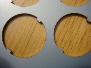
After removing the buttons you will notice 2 tabs on each button hole. Youll have to grind those off. This is what it should look like when your done. Also i sprayed the plate with some rustoleom to help prevent rust in the future. Note: You will not have to modify the start/select holes.
![DSC01751.jpg]()
![DSC01758.jpg]()
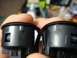
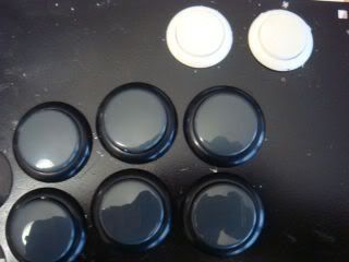
The plate is ready for the buttons to be installed. But youll run into a problem. The buttons will snap in but wont sit flush with the plate. To fix this youll have the grind down 4 tabs that are on the button. Once you do this, they will snap in perfectly and sit completely flat.
![DSC01760.jpg]()
![DSC01761.jpg]()
Now that the buttons are mounted youll need to get the JLF ready to be mounted. First thing youll have to do is remove the mounting plate if your JLF came with one. Do this by removing the 4 screws holding it on. Make sure you use a screwdriver that fits perfectly. These screws are notorious for stipping. Once you have done that youll need to remove the gate by lifting the tabs and pulling it. After that youll have to drill out 4 tabs so the mounting screws will be able to go through. I marked with black marker where to drill.
![DSC01756.jpg]()
![DSC01757.jpg]()
![DSC01763.jpg]()
![DSC01764.jpg]()
Reinstall the gate on the JLF. Now the holes you just drilled should line up with the screw holes on the mounting plate on the top plate. Using the 4 long screws you took off the hori stick, secure the JLF.
![DSC01767.jpg]()
This next step i forgot to take alot of pics. but its pretty simple.
You have to wire up the pcb. What i did was cut 16 pieces of wire the same length. Then i stripped one side of the wire. Then twist the exposed wire. Not its ready to be soldered onto the pcb. Solder the onto the green side of the pcb. Once youve done that you will have alittle extra wire sticking up, use pliers to cut it off. Do this for all the buttons you gonna be using. When done, strip the other side of the wire and crimp you quick disconnects on. Then connect them to the buttons. doesnt matter which prong is the ground on the buttons.
![DSC01753.jpg]()
![DSC01755.jpg]()
![DSC01765.jpg]()
![DSC01770.jpg]()
Now to wire up the joystick. I used a terminal to do this. I put all the common grounds from the pcb in one slot and wired it to the ground from the joystick. On the rest of the wiring i followed this-
![DSC01769.jpg]()
![DSC01768.jpg]()
![DSC01771.jpg]()
After that close it up and test it to make sure everything on your Stick works.
Heres my finished stick-
![DSC01775.jpg]()
Artwork-
Use this template-
http://fs01n2.sendspace.com/dl/1c693f9152abd4507ba0e781ec1fc0db/49bc4a0a7508b8f9/znri2d/Template%20T5.psd
When you take it to get printed ask them to print it on legal paper, but NOT to resize it to fit the media.
On mine i first printed it on regular paper, cut it out. then i lamilabeled it.
Hope this helps.
![jlfpcbpinouts.jpg]()
Since alot of the pics are down and so many people are asking the same question. I decided to post up pics from my mod i did a couple of days ago. A Lot of the info is on this one post, so hope this helps you guys out.
(These are the tools and materials i used, you can use different sizes or whatever is available to you)
Materials-
JLF-TP-8T(with harness)
OBSF-30 buttons
OBSF-24 buttons
Sanwa 30mm Hole plugs
.187 quick disconnects
22 gauge strand wire
Solder(rosin core)
Tools-
Solder Iron
Solder Sucker
Solder wick
Wire stripper
Wire Crimper
Drill
7/64 drill bit
9/32 socket w/extension
glue gun
Grinder/Dremel/File(whichever one is available)
Pliers/cutters
This is what your starting with.
Using a Phillips head screw driver take the 8 screws out. Using the socket take the nuts off that are holding the top plate on.


This is what it looks like once you open it up

Next you want you take the 4 screws out that are holding the Hori stick onto the mounting bracket. Make sure you save these, youll need them to install the JLF. After taking the screws out, cut all 8 wires that are soldered to the switches. Cut as close to the switches as possible.


Hope you watched a couple of videos on YouTube about soldering/desoldering. Your gonna have to desolder all 10 buttons. It helps to wiggle/pull slightly on the pcb when desoldering to get the board to lift up.


Once you have the pcb off you will see all the buttons. Notice the tabs, push those in to remove the buttons from the plate.


After removing the buttons you will notice 2 tabs on each button hole. Youll have to grind those off. This is what it should look like when your done. Also i sprayed the plate with some rustoleom to help prevent rust in the future. Note: You will not have to modify the start/select holes.

The plate is ready for the buttons to be installed. But youll run into a problem. The buttons will snap in but wont sit flush with the plate. To fix this youll have the grind down 4 tabs that are on the button. Once you do this, they will snap in perfectly and sit completely flat.
Now that the buttons are mounted youll need to get the JLF ready to be mounted. First thing youll have to do is remove the mounting plate if your JLF came with one. Do this by removing the 4 screws holding it on. Make sure you use a screwdriver that fits perfectly. These screws are notorious for stipping. Once you have done that youll need to remove the gate by lifting the tabs and pulling it. After that youll have to drill out 4 tabs so the mounting screws will be able to go through. I marked with black marker where to drill.


Reinstall the gate on the JLF. Now the holes you just drilled should line up with the screw holes on the mounting plate on the top plate. Using the 4 long screws you took off the hori stick, secure the JLF.

This next step i forgot to take alot of pics. but its pretty simple.
You have to wire up the pcb. What i did was cut 16 pieces of wire the same length. Then i stripped one side of the wire. Then twist the exposed wire. Not its ready to be soldered onto the pcb. Solder the onto the green side of the pcb. Once youve done that you will have alittle extra wire sticking up, use pliers to cut it off. Do this for all the buttons you gonna be using. When done, strip the other side of the wire and crimp you quick disconnects on. Then connect them to the buttons. doesnt matter which prong is the ground on the buttons.


Now to wire up the joystick. I used a terminal to do this. I put all the common grounds from the pcb in one slot and wired it to the ground from the joystick. On the rest of the wiring i followed this-


After that close it up and test it to make sure everything on your Stick works.
Heres my finished stick-

Artwork-
Use this template-
http://fs01n2.sendspace.com/dl/1c693f9152abd4507ba0e781ec1fc0db/49bc4a0a7508b8f9/znri2d/Template%20T5.psd
When you take it to get printed ask them to print it on legal paper, but NOT to resize it to fit the media.
On mine i first printed it on regular paper, cut it out. then i lamilabeled it.
Hope this helps.
Here's an image explaining the relation between wiring in the Sanwa and Seimitsu 5-pin wire harnesses.DominoLogic, post: wrote:im not tingboy but i have put a JLF in my t5 so i think i can answer this correctly
first a useful picture found in sanwa/seimitsu faq
http://i57.photobucket.com/albums/g217/NiteWalkerGR/Misc%20Pics/sanwakopplingen.jpg
quote from from a t5 modding tutorial:
"Wiring layout.
(reading from the top down on the back side of the PCB where the joystick wires come from)
Of each pair of colored wires, the first one is the common ground.
Common grounds are all soldered to the prong on the microswitch that reads "COM"
Joystick wires will be soldered to the prong that reads "NO" for "normally open"
Therefore the eight wires will equate to:
8 as seen on the PCB
Grey 1 = Common ground
Grey 2 = Joystick Right
White 1 = Common ground
White 2 = Joystick Left
Yellow 1 = Common ground
Yellow 2 = Joystick Down
Red 1 = Common ground
Red 2 = Joystick Up
1 as seen on the PCB"
basically what you do is connect the black wire thats on the 5 pin harness to any one of the common ground wires coming out of the PCB. any ground wire is ok because theyre all at the same potential (thats what common ground means). the other ground wires you can tie off or just leave them hanging (probably better to tie it off).
then you just hook up the colored direction wires to the other wires coming out of the PCB depending how you put the joystick in. for example if you put in the stick with the harness facing DOWN, then your red wire coming out of the harness (joystick right) would be connected to the 2nd gray wire on the pcb.
and yes you can still use the 4 mounting holes
