ive cracked 4 balltops.. 2 seimitsu blue bubble tops and 1 dark blue clear sanwa ball top and 1 smoke clear sanwa.. the blue ones were on my chun li stick and the smoke one was on my SCV stick.. how do i prevent the balltop from cracking at the base?
↧
cracked ball tops..
↧
Tech help with the Injustice Fight Stick and applying Uila S Flash LEDs on clear Seimitsus
Hey, everyone, first time attempting to make buttons be in other various LED colors based on which button(s) are pushed, like in this video:
![image]()
I also stumbled upon this video, too:
![image]()
However, I am at a loss as which wire connects to what from the Injustice stick to the Sparky PWM PCB and also wanted to know how to change the LED colors. As stated, I have the Uila S Flash LEDs along with clear Seimitsus. I am also wondering what the Sparkfun PCB is for as I also got that along with the Uila S Flash LEDs I bought recently. Any help would be greatly appreciated!
I also stumbled upon this video, too:
However, I am at a loss as which wire connects to what from the Injustice stick to the Sparky PWM PCB and also wanted to know how to change the LED colors. As stated, I have the Uila S Flash LEDs along with clear Seimitsus. I am also wondering what the Sparkfun PCB is for as I also got that along with the Uila S Flash LEDs I bought recently. Any help would be greatly appreciated!
↧
↧
CUSTOM FS HELP JOYSTICK PROBLEMS (1st time poster/modder)
First of all, this is my first post. Second of all I apologize if this post is in the wrong area. And thirdly, I tried looking for an answer for my specific problem and can't seem to find anything that seems to be my unique problem.
Now, After much research and months of ordering parts at a time I finally got all the parts needed to build a custom FS. Everything was going well, UNTIL i got to the joystick. All the buttons worked perfectly and were recognized when inputting them into my PC's device menu (the one where you can see what direction you're pushing and can calibrate it and such. Anyway, for some reason the JLF, doesn't recognize any of the inputs. I found an old picture on SRK about how to wire it i think it was by rtdzign i think his name was, and it didn't work ( I tried all combinations just incase i was being stupid). For some reason, only 3 inputs come out, and those 3 are all wrong, any other inputs do not show up at all. Example: when i hit left on my joystick, it registers down, when i hit back+up it registers up, and when i hit down+back it registers Forward+down. I'm not sure why this happened and if its the pcb or the joystick itself. I wouldn't think its the pcb because the buttons work fine, but I am new to this so any hlep would b appreciated asap, as I am in need of this FS before march 2nd if possible and 8th at the latest:(.
Joystick I bought is Sanwa JLF-TP-8YT Joystick from Focus Attack.
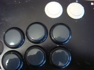
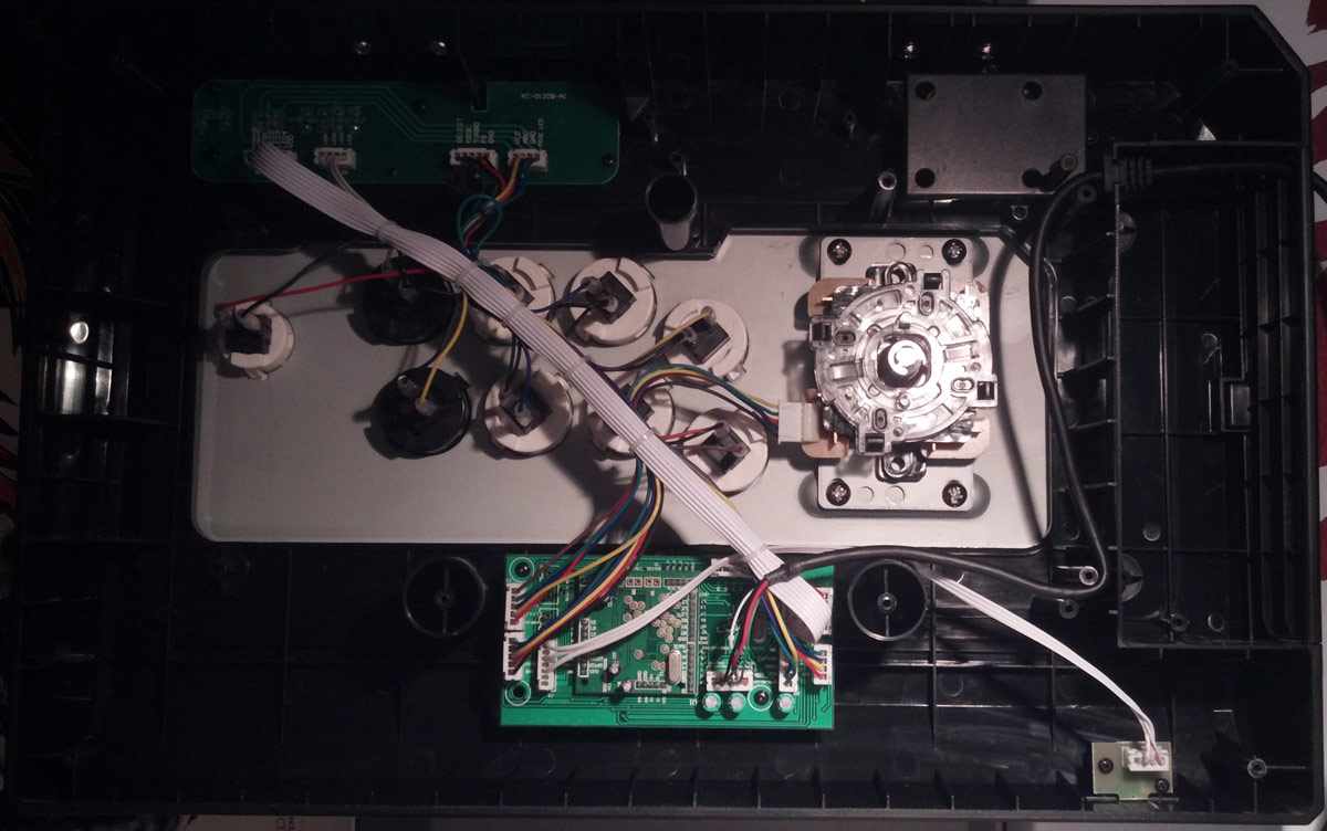
Images for/about my problem:
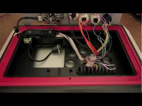
The Harness
[img]![1nyds1.jpg]()
PCB:
![2hgy5af.jpg]()
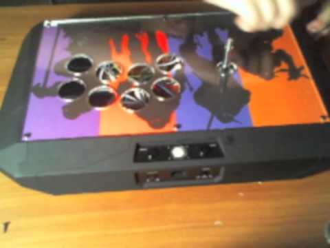
The art: Just so this post isnt a total bore XD
![dzfg4m.jpg]()
Now, After much research and months of ordering parts at a time I finally got all the parts needed to build a custom FS. Everything was going well, UNTIL i got to the joystick. All the buttons worked perfectly and were recognized when inputting them into my PC's device menu (the one where you can see what direction you're pushing and can calibrate it and such. Anyway, for some reason the JLF, doesn't recognize any of the inputs. I found an old picture on SRK about how to wire it i think it was by rtdzign i think his name was, and it didn't work ( I tried all combinations just incase i was being stupid). For some reason, only 3 inputs come out, and those 3 are all wrong, any other inputs do not show up at all. Example: when i hit left on my joystick, it registers down, when i hit back+up it registers up, and when i hit down+back it registers Forward+down. I'm not sure why this happened and if its the pcb or the joystick itself. I wouldn't think its the pcb because the buttons work fine, but I am new to this so any hlep would b appreciated asap, as I am in need of this FS before march 2nd if possible and 8th at the latest:(.
Joystick I bought is Sanwa JLF-TP-8YT Joystick from Focus Attack.
Images for/about my problem:
The Harness
[img]

PCB:

The art: Just so this post isnt a total bore XD

↧
Sanwa JLF with Link installed Problem
Hey guys, I recently installed a Link on my stock TE and I noticed that it now has a huge deadzone. I've tried it with and without the 2nd dust washer, and it feels the same.
I can move the stick quite bit before it engages any of the switches. I'm not sure what the problem is... it's beginning to get really frustrating. If it makes a difference, I'm using a bat top (sacrilege, I know).
Please help!
I can move the stick quite bit before it engages any of the switches. I'm not sure what the problem is... it's beginning to get really frustrating. If it makes a difference, I'm using a bat top (sacrilege, I know).
Please help!
↧
Hori T5: Modding Tutorial
Thank you for the update AJtheMishima
Since alot of the pics are down and so many people are asking the same question. I decided to post up pics from my mod i did a couple of days ago. A Lot of the info is on this one post, so hope this helps you guys out.
(These are the tools and materials i used, you can use different sizes or whatever is available to you)
Materials-
JLF-TP-8T(with harness)
OBSF-30 buttons
OBSF-24 buttons
Sanwa 30mm Hole plugs
.187 quick disconnects
22 gauge strand wire
Solder(rosin core)
Tools-
Solder Iron
Solder Sucker
Solder wick
Wire stripper
Wire Crimper
Drill
7/64 drill bit
9/32 socket w/extension
glue gun
Grinder/Dremel/File(whichever one is available)
Pliers/cutters
This is what your starting with.
Using a Phillips head screw driver take the 8 screws out. Using the socket take the nuts off that are holding the top plate on.
![DSC01736.jpg]()
![DSC01737.jpg]()
![DSC01738.jpg]()
This is what it looks like once you open it up
![DSC01739.jpg]()
Next you want you take the 4 screws out that are holding the Hori stick onto the mounting bracket. Make sure you save these, youll need them to install the JLF. After taking the screws out, cut all 8 wires that are soldered to the switches. Cut as close to the switches as possible.
![DSC01740.jpg]()
![DSC01742.jpg]()
Hope you watched a couple of videos on YouTube about soldering/desoldering. Your gonna have to desolder all 10 buttons. It helps to wiggle/pull slightly on the pcb when desoldering to get the board to lift up.
![DSC01746.jpg]()
![DSC01747.jpg]()
Once you have the pcb off you will see all the buttons. Notice the tabs, push those in to remove the buttons from the plate.
![DSC01748.jpg]()
![DSC01750.jpg]()
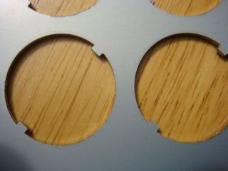
After removing the buttons you will notice 2 tabs on each button hole. Youll have to grind those off. This is what it should look like when your done. Also i sprayed the plate with some rustoleom to help prevent rust in the future. Note: You will not have to modify the start/select holes.
![DSC01751.jpg]()
![DSC01758.jpg]()
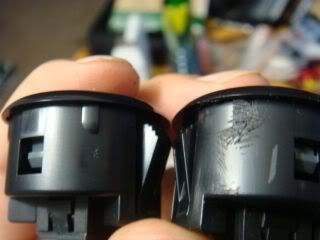
The plate is ready for the buttons to be installed. But youll run into a problem. The buttons will snap in but wont sit flush with the plate. To fix this youll have the grind down 4 tabs that are on the button. Once you do this, they will snap in perfectly and sit completely flat.
![DSC01760.jpg]()
![DSC01761.jpg]()
Now that the buttons are mounted youll need to get the JLF ready to be mounted. First thing youll have to do is remove the mounting plate if your JLF came with one. Do this by removing the 4 screws holding it on. Make sure you use a screwdriver that fits perfectly. These screws are notorious for stipping. Once you have done that youll need to remove the gate by lifting the tabs and pulling it. After that youll have to drill out 4 tabs so the mounting screws will be able to go through. I marked with black marker where to drill.
![DSC01756.jpg]()
![DSC01757.jpg]()
![DSC01763.jpg]()
![DSC01764.jpg]()
Reinstall the gate on the JLF. Now the holes you just drilled should line up with the screw holes on the mounting plate on the top plate. Using the 4 long screws you took off the hori stick, secure the JLF.
![DSC01767.jpg]()
This next step i forgot to take alot of pics. but its pretty simple.
You have to wire up the pcb. What i did was cut 16 pieces of wire the same length. Then i stripped one side of the wire. Then twist the exposed wire. Not its ready to be soldered onto the pcb. Solder the onto the green side of the pcb. Once youve done that you will have alittle extra wire sticking up, use pliers to cut it off. Do this for all the buttons you gonna be using. When done, strip the other side of the wire and crimp you quick disconnects on. Then connect them to the buttons. doesnt matter which prong is the ground on the buttons.
![DSC01753.jpg]()
![DSC01755.jpg]()
![DSC01765.jpg]()
![DSC01770.jpg]()
Now to wire up the joystick. I used a terminal to do this. I put all the common grounds from the pcb in one slot and wired it to the ground from the joystick. On the rest of the wiring i followed this-
![DSC01769.jpg]()
![DSC01768.jpg]()
![DSC01771.jpg]()
After that close it up and test it to make sure everything on your Stick works.
Heres my finished stick-
![DSC01775.jpg]()
Artwork-
Use this template-
http://fs01n2.sendspace.com/dl/1c693f9152abd4507ba0e781ec1fc0db/49bc4a0a7508b8f9/znri2d/Template%20T5.psd
When you take it to get printed ask them to print it on legal paper, but NOT to resize it to fit the media.
On mine i first printed it on regular paper, cut it out. then i lamilabeled it.
Hope this helps.
![jlfpcbpinouts.jpg]()
Since alot of the pics are down and so many people are asking the same question. I decided to post up pics from my mod i did a couple of days ago. A Lot of the info is on this one post, so hope this helps you guys out.
(These are the tools and materials i used, you can use different sizes or whatever is available to you)
Materials-
JLF-TP-8T(with harness)
OBSF-30 buttons
OBSF-24 buttons
Sanwa 30mm Hole plugs
.187 quick disconnects
22 gauge strand wire
Solder(rosin core)
Tools-
Solder Iron
Solder Sucker
Solder wick
Wire stripper
Wire Crimper
Drill
7/64 drill bit
9/32 socket w/extension
glue gun
Grinder/Dremel/File(whichever one is available)
Pliers/cutters
This is what your starting with.
Using a Phillips head screw driver take the 8 screws out. Using the socket take the nuts off that are holding the top plate on.


This is what it looks like once you open it up

Next you want you take the 4 screws out that are holding the Hori stick onto the mounting bracket. Make sure you save these, youll need them to install the JLF. After taking the screws out, cut all 8 wires that are soldered to the switches. Cut as close to the switches as possible.


Hope you watched a couple of videos on YouTube about soldering/desoldering. Your gonna have to desolder all 10 buttons. It helps to wiggle/pull slightly on the pcb when desoldering to get the board to lift up.


Once you have the pcb off you will see all the buttons. Notice the tabs, push those in to remove the buttons from the plate.


After removing the buttons you will notice 2 tabs on each button hole. Youll have to grind those off. This is what it should look like when your done. Also i sprayed the plate with some rustoleom to help prevent rust in the future. Note: You will not have to modify the start/select holes.

The plate is ready for the buttons to be installed. But youll run into a problem. The buttons will snap in but wont sit flush with the plate. To fix this youll have the grind down 4 tabs that are on the button. Once you do this, they will snap in perfectly and sit completely flat.
Now that the buttons are mounted youll need to get the JLF ready to be mounted. First thing youll have to do is remove the mounting plate if your JLF came with one. Do this by removing the 4 screws holding it on. Make sure you use a screwdriver that fits perfectly. These screws are notorious for stipping. Once you have done that youll need to remove the gate by lifting the tabs and pulling it. After that youll have to drill out 4 tabs so the mounting screws will be able to go through. I marked with black marker where to drill.


Reinstall the gate on the JLF. Now the holes you just drilled should line up with the screw holes on the mounting plate on the top plate. Using the 4 long screws you took off the hori stick, secure the JLF.

This next step i forgot to take alot of pics. but its pretty simple.
You have to wire up the pcb. What i did was cut 16 pieces of wire the same length. Then i stripped one side of the wire. Then twist the exposed wire. Not its ready to be soldered onto the pcb. Solder the onto the green side of the pcb. Once youve done that you will have alittle extra wire sticking up, use pliers to cut it off. Do this for all the buttons you gonna be using. When done, strip the other side of the wire and crimp you quick disconnects on. Then connect them to the buttons. doesnt matter which prong is the ground on the buttons.


Now to wire up the joystick. I used a terminal to do this. I put all the common grounds from the pcb in one slot and wired it to the ground from the joystick. On the rest of the wiring i followed this-


After that close it up and test it to make sure everything on your Stick works.
Heres my finished stick-

Artwork-
Use this template-
http://fs01n2.sendspace.com/dl/1c693f9152abd4507ba0e781ec1fc0db/49bc4a0a7508b8f9/znri2d/Template%20T5.psd
When you take it to get printed ask them to print it on legal paper, but NOT to resize it to fit the media.
On mine i first printed it on regular paper, cut it out. then i lamilabeled it.
Hope this helps.
Here's an image explaining the relation between wiring in the Sanwa and Seimitsu 5-pin wire harnesses.DominoLogic, post: wrote:im not tingboy but i have put a JLF in my t5 so i think i can answer this correctly
first a useful picture found in sanwa/seimitsu faq
http://i57.photobucket.com/albums/g217/NiteWalkerGR/Misc%20Pics/sanwakopplingen.jpg
quote from from a t5 modding tutorial:
"Wiring layout.
(reading from the top down on the back side of the PCB where the joystick wires come from)
Of each pair of colored wires, the first one is the common ground.
Common grounds are all soldered to the prong on the microswitch that reads "COM"
Joystick wires will be soldered to the prong that reads "NO" for "normally open"
Therefore the eight wires will equate to:
8 as seen on the PCB
Grey 1 = Common ground
Grey 2 = Joystick Right
White 1 = Common ground
White 2 = Joystick Left
Yellow 1 = Common ground
Yellow 2 = Joystick Down
Red 1 = Common ground
Red 2 = Joystick Up
1 as seen on the PCB"
basically what you do is connect the black wire thats on the 5 pin harness to any one of the common ground wires coming out of the PCB. any ground wire is ok because theyre all at the same potential (thats what common ground means). the other ground wires you can tie off or just leave them hanging (probably better to tie it off).
then you just hook up the colored direction wires to the other wires coming out of the PCB depending how you put the joystick in. for example if you put in the stick with the harness facing DOWN, then your red wire coming out of the harness (joystick right) would be connected to the 2nd gray wire on the pcb.
and yes you can still use the 4 mounting holes

↧
↧
Joystick replacement advice for a Nakitech Joystick
Hey all, I just picked up a cheap stick that I'm looking to mod with better parts.
The stick is the Nakitech Wireless Ultimate Fighting Stick for PS2/Xbox. Its apparently the same body design as the Saulabi SPS-1000.
It's a strange stick with very unusual features. Not only is it wireless, it also has these weird surface mount thumbsticks so analog only menus can be navigated, and it even has a rumble motor.
The buttons are 30mm stock, making them ideal for drop-in Sanwa 30mm buttons. I've already done that.
What I want to do is replace the joystick with something, ANYTHING better, but the holes are very different from sticks I've modded before. To accommodate the rumble motor at the end of the stick, the whole casing for the joystick itself is large.
The screwholes are in a square shape, each located 6.5cm from each.
I don't want any visible holes through the top of the case.
Does anyone know of a Sanwa or Seimitsu joystick that would fit these holes?
I can provide pics if needed.
thanks.
↧
Select/Back Linking (plinking) with a Qanba Q4raf [is it possible]
Select/Back Linking (plinking) with a Qanba Q4raf [is it possible]?
I'm just curious if it can be done. I opened my stick and my inner thoughts say yes but my rationality says no.
Note: I dont know anything about modding sticks
Edit:
So the main concern is the fact that the select button is wired into a seperate pcb directly vs a button like other madcatz sticks
Interior:
![26_qanbareview05.jpg]()
I know how to do it with a madcatz stick with start and select buttons i just heard people say you cant since the select button is connected to a pcb, then connected to the main pcb.
Was that person wrong or is it still possible?
I have no major soldering/electronics experience but im an engineer so im sure i can figure it out if its doable
I'm just curious if it can be done. I opened my stick and my inner thoughts say yes but my rationality says no.
Note: I dont know anything about modding sticks
Edit:
So the main concern is the fact that the select button is wired into a seperate pcb directly vs a button like other madcatz sticks
Interior:
I know how to do it with a madcatz stick with start and select buttons i just heard people say you cant since the select button is connected to a pcb, then connected to the main pcb.
Was that person wrong or is it still possible?
I have no major soldering/electronics experience but im an engineer so im sure i can figure it out if its doable
↧
HBFS30-G2 Pre-Order will be open in 8/15 ~All New Arcade Button~Update: 14/8/2013
Dear Game Geeks:
Thanks to the support of the many players and funders,
GAMERFINGER reached goal at the last season-"Provide excellent fighting game experience for FTG players."
For us, this is a very important achievement.
Gives us driving force, keep moving and develop innovative.
And we absorb the player feedback into new creativity.
HBFS-30 to promote FTG players a new fun experience.
But we're not complacent.
Has been redesigned and improved for several months,
We build more reliable Button ---- HBFS-G2 Series
Including HBFS-30, HBFS-24, HBFSC-30
More details will release soon.
![HBFSG2%2520%25282%2529.jpg]()
Update: 14/6/2013
<HBFS-G2>
Based excellent sensitivity, significantly reduce the noise, diverse power options.
HBFS-G2 has further enhanced the ease of installation.
We have streamlined the steps of button install.
The all new structure design, get rid of adapter plugs.
Plug terminals and button into one.
Do not need to change the existing wirings system,
It's important that no more annoying problem of loose wires.
Of course, the more easy when you changing different microswitch.
![G2plug.gif]()
Update: 17/6/2013
<HBFSC-30>
Many players in pursuing personal style fighting controller.
Players use creativity and art in decorating their weapons.
We listen to the needs of players, and practice ideas.
Now, HBFSC-30's plug can embed image.
![HBFSC.jpg]()
Sorry for that our web shop opening time has been delayed.
Now, We're almost done!!
![998047_548357088559425_363672357_n.jpg]()
And We are get ready to release HBFS24!!
http://www.gamerfinger.com/hbfs24.html
Update: 14/8/2013
![preorder.jpg]()
Thank you Geek Fighter :
Because of your support, we reach the first goal in the last year.
HBFS-30 was satisfy the expectations of many gamers.
We improve our design though your sponsorship and support.
We got great motivation, whether the words of encouragement or suggestions about shortcomings.
"We know we can do it better."
Eventually,
Here is our latest product HBFS-30 G2 & HBFS-24.
![HBFSG2.jpg]()
HBFS-30 G2 got something new; The new structural design, Integrally molded connectors, new colors, and more detail.
In addition, HBFS-24 is specially built for the HitBox control layout players.
You must experience yourself.
More Info-GamerFinger Office website
We will open pre-order on 8/15~ 9/15
Delivery is expected to ship in late September.
The early bird discount of 15% off ; Please just seize the opportunity.
Furthermore, express our gratitude to you.
If you are a funder before, We prepared additional coupons to you, please just check your mailbox.
![LOGO-01.png]()
GET HBFS-30 G2 NOW
Hope you enjoy it!
Sincerely thank
GAMERFINGER -Pei Kao
Thanks to the support of the many players and funders,
GAMERFINGER reached goal at the last season-"Provide excellent fighting game experience for FTG players."
For us, this is a very important achievement.
Gives us driving force, keep moving and develop innovative.
And we absorb the player feedback into new creativity.
HBFS-30 to promote FTG players a new fun experience.
But we're not complacent.
Has been redesigned and improved for several months,
We build more reliable Button ---- HBFS-G2 Series
Including HBFS-30, HBFS-24, HBFSC-30
More details will release soon.

Update: 14/6/2013
<HBFS-G2>
Based excellent sensitivity, significantly reduce the noise, diverse power options.
HBFS-G2 has further enhanced the ease of installation.
We have streamlined the steps of button install.
The all new structure design, get rid of adapter plugs.
Plug terminals and button into one.
Do not need to change the existing wirings system,
It's important that no more annoying problem of loose wires.
Of course, the more easy when you changing different microswitch.

Update: 17/6/2013
<HBFSC-30>
Many players in pursuing personal style fighting controller.
Players use creativity and art in decorating their weapons.
We listen to the needs of players, and practice ideas.
Now, HBFSC-30's plug can embed image.

Sorry for that our web shop opening time has been delayed.
Now, We're almost done!!

And We are get ready to release HBFS24!!
http://www.gamerfinger.com/hbfs24.html
Update: 14/8/2013

Thank you Geek Fighter :
Because of your support, we reach the first goal in the last year.
HBFS-30 was satisfy the expectations of many gamers.
We improve our design though your sponsorship and support.
We got great motivation, whether the words of encouragement or suggestions about shortcomings.
"We know we can do it better."
Eventually,
Here is our latest product HBFS-30 G2 & HBFS-24.

HBFS-30 G2 got something new; The new structural design, Integrally molded connectors, new colors, and more detail.
In addition, HBFS-24 is specially built for the HitBox control layout players.
You must experience yourself.
More Info-GamerFinger Office website
We will open pre-order on 8/15~ 9/15
Delivery is expected to ship in late September.
The early bird discount of 15% off ; Please just seize the opportunity.
Furthermore, express our gratitude to you.
If you are a funder before, We prepared additional coupons to you, please just check your mailbox.
GET HBFS-30 G2 NOW
Hope you enjoy it!
Sincerely thank
GAMERFINGER -Pei Kao
↧
2 Fight Sticks, same MAC address???
So here's something weird.
Just finished modding 2x new Paewang Revolution Sticks. Both working just fine until... we try to use both of them at the same time (on Xbox 360)
Only one stick registers as being plugged in. Seems that whichever one is plugged in 2nd, take precedence as Player 1, leaving the 1st controller unrecognised. Player 2 never comes up.
I've tried both sticks with other controllers, other fights sticks and even my current stick which is the same brand purchased about 18 months ago, and everything works just fine.
Plug both Paewangs in at the same time however, and only one registers. I think both PCB's have the same MAC address.
Is this possible? Does anyone have any solutions? Please help.
I'm thinking the only fix is getting another PCB, which is going to be a pain with a Comp around the corner and I don't really want to spend time rewiring another PCB in.
Thoughts tech heads? Thanks.
↧
↧
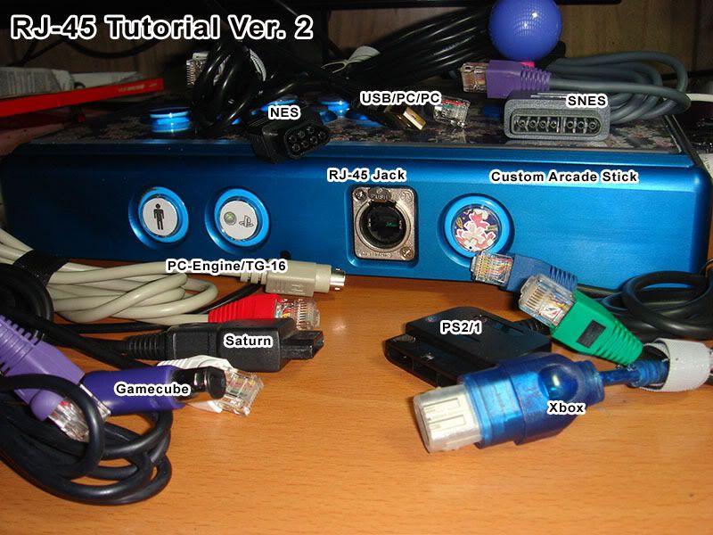
RJ-45 Multi Console Cthulhu Arcade Stick Tutorial Ver.2
Edit:Also Dreamcast and 3DO
Intro
This post is a rewrite of Acceptable Risk?s RJ-45 Tutorial. This was posted to include new info such as recent console support added because the pinouts are spread out in the Cthulhu thread. Also I instead uses a Pass through over a keystone punch down type jack.
The MC Cthulhu is a purpose built PCB for hooking up with arcade joystick components. To work with different consoles, you only need to solder wires from a controller extension cable to the appropriate spots. If you look at the top op the pcb there are 3 rows of solder points with columns labled "GABCDEFV". Each extension cable wire must be soldered on to the appropriate column. When plugged in, the MC Cthulhu PCB can autodectect what system it is plugged into and then make your joystick work for that supported system. Be sure to download the latest firmware to ensure that all of the console cables you make will be compatible.
Originally the MC Cthulhu was able to support 5 consoles using 3 cables, therefore only 3 rows, but now it has grown to include many systems. Because there are 8 columns for system cables a Ethernet jack was a natural fit. The connecter used is typically an RJ-45. If you want to do a dual mod with Xbox 360 pad then you should check out this tutorial.
http://shoryuken.com/forum/index.php?threads/rj-45-mc-cthulhu-imp-xbox-360-dual-mod-tutorial-diagram.94875/
Kitty info Update: If you dual modded your stick with a Kitty board, they come preinstalled with a RJ-45 jack. If you connect that to a RJ-45 pass through, then you can use the same cable pinouts for making your own custom cable.
Begin Tutorial
Spoiler:
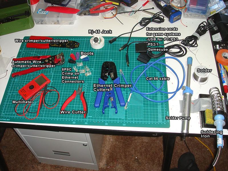
Supplies List:
MC Cthulhu
Arcade stick case and buttons.
Soldering Iron and Soldering supplies
Digital Multimeter (Recommended feature: beeping continuity tester)
Wire stripper/cutter
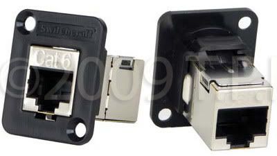
Neutrik or SwitchCraft RJ-45 Jack.
Cat 5 or Cat 6 ethernet cable. For pass through you need a cable with a connector at the end.
Cat 5/6 Crimper and wire cutter/stripper.
Cat 5/6 8P8C crimp on Connectors.
Extension cables for systems you want to use
24mm drill bit (forstner or Holesaw) for mounting hole and drill.
(optional)
Ethernet boots
Neutrik ruggedized boots for use with Neutrik Jack.
Hammer
![RJ-45_Tools_Supplies.jpg]()
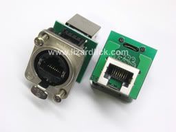
Part 1: Mounting the RJ-45.
I think it was Robokrikit that first linked the community to these. These are Neutrik RJ-45 panel mount jacks, available at lizardlick.com.
![ne8fdp_thumb.jpg]()
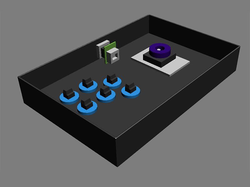
If you have a Plastic arcade stick Like a TE or SE or Hori
You will need to find a suitable place to drill a 24mm hole. 15/16 inches is equivalent to 24mm. Make sure before you drill a hole that you have enough space inside for the internal parts and can plug in the cable to it without obstruction.
![Placing-Neutrik-Hole.jpg]()
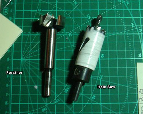
Pictured is a Hole Saw and a Forstner bit. A hole Saw is great for plastic and metal, and will work for wood, you will have to clear out the material out of the bit with a screwdriver. Forstners are great for wood an plastic, but do not attempt to cut metal with a forstner bit.
So if you drill a 24mm hole you can then use the mounting plate to drill the 2 mounting holes.
![DrillBits.jpg]()
For a wood case it is recommended that you use a switchcraft RJ-45. I think it was Voltech that first used these.
![SwitchCraftRJ-45.jpg]()
If you must mount the Neutrik in a wood case look to a post below.
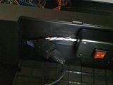
Drill free option Update:
Recently I modded a VLX but this can also be used with a TE or any stick with a cord notch. I didn't want to drill into my VLX case so Instead I used an Ethernet coupler and hid that away in the cord compartment. I tied a knot in my ethernet cord so that the cord would not be pulled out of the notch used for the default usb cord. For a TE, you would cut off one end of the ethernet cable and then feed it through the hole previously used by the USB cable. After it is through the hole tie a knot in it. With the cut end on the inside you can then solder to the G-V row.
![th_1b827ab6.jpg]()
![th_2cf280a1.jpg]()
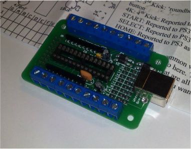
Part 2: Soldering on the ethernet cable to the MC Cthulhu
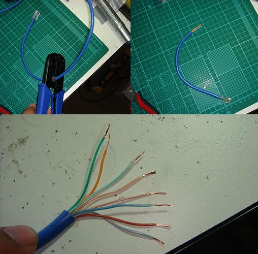
To start you would cut off maybe a foot off a cat5 or cat6 ethernet cable. The length should be long enough to reach where the RJ-45 jack is on your arcade stick. Strip off maybe a inch or two off the outer insulation and untwist the cables.
![CutStripCat5.jpg]()
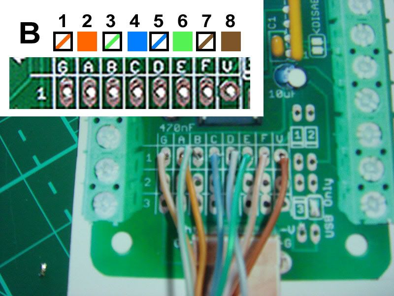
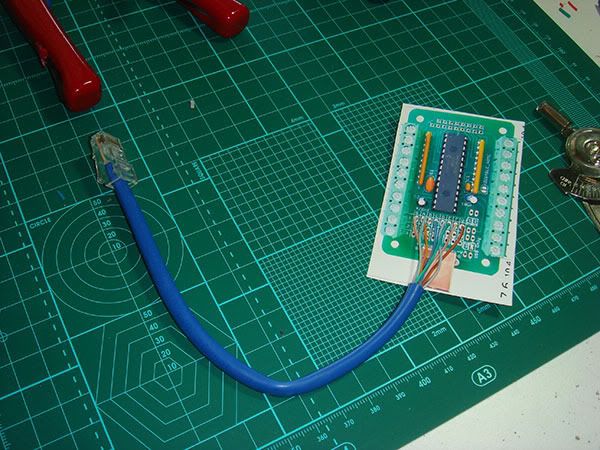
You want to use Ethernet Tybe B layout as most networking cables come in that wiring order. You need to take the 8 wires and strip off 5 mm off the ends and solder them to row 1 using the following diagram. If the are stranded like pictured above then you want to twist and tin each cable end with some solder so it goes in easier. Each of those colored wires corresponds to a letter on the GABCDEFV row.
![WiringEthernetColorsTo_GV_Row.jpg]()
It also helps if you solder on to an actual MC board instead of a picture of the board. (note pictured on the paper is a ps3 cthulhu, which is identical in appearance except for 4 diodes to the right of the G-V rows)
![Cat5eSolderedonBoard.jpg]()
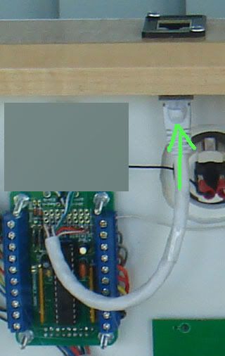
Now you just plug it into the RJ-45 pass through port.
![PlugIt_intoPort.jpg]()
MC Cthulhu
Arcade stick case and buttons.
Soldering Iron and Soldering supplies
Digital Multimeter (Recommended feature: beeping continuity tester)
Wire stripper/cutter
Neutrik or SwitchCraft RJ-45 Jack.
Cat 5 or Cat 6 ethernet cable. For pass through you need a cable with a connector at the end.
Cat 5/6 Crimper and wire cutter/stripper.
Cat 5/6 8P8C crimp on Connectors.
Extension cables for systems you want to use
24mm drill bit (forstner or Holesaw) for mounting hole and drill.
(optional)
Ethernet boots
Neutrik ruggedized boots for use with Neutrik Jack.
Hammer
Part 1: Mounting the RJ-45.
I think it was Robokrikit that first linked the community to these. These are Neutrik RJ-45 panel mount jacks, available at lizardlick.com.
If you have a Plastic arcade stick Like a TE or SE or Hori
You will need to find a suitable place to drill a 24mm hole. 15/16 inches is equivalent to 24mm. Make sure before you drill a hole that you have enough space inside for the internal parts and can plug in the cable to it without obstruction.
Pictured is a Hole Saw and a Forstner bit. A hole Saw is great for plastic and metal, and will work for wood, you will have to clear out the material out of the bit with a screwdriver. Forstners are great for wood an plastic, but do not attempt to cut metal with a forstner bit.
So if you drill a 24mm hole you can then use the mounting plate to drill the 2 mounting holes.
For a wood case it is recommended that you use a switchcraft RJ-45. I think it was Voltech that first used these.
If you must mount the Neutrik in a wood case look to a post below.
Drill free option Update:
Recently I modded a VLX but this can also be used with a TE or any stick with a cord notch. I didn't want to drill into my VLX case so Instead I used an Ethernet coupler and hid that away in the cord compartment. I tied a knot in my ethernet cord so that the cord would not be pulled out of the notch used for the default usb cord. For a TE, you would cut off one end of the ethernet cable and then feed it through the hole previously used by the USB cable. After it is through the hole tie a knot in it. With the cut end on the inside you can then solder to the G-V row.

Part 2: Soldering on the ethernet cable to the MC Cthulhu
To start you would cut off maybe a foot off a cat5 or cat6 ethernet cable. The length should be long enough to reach where the RJ-45 jack is on your arcade stick. Strip off maybe a inch or two off the outer insulation and untwist the cables.
You want to use Ethernet Tybe B layout as most networking cables come in that wiring order. You need to take the 8 wires and strip off 5 mm off the ends and solder them to row 1 using the following diagram. If the are stranded like pictured above then you want to twist and tin each cable end with some solder so it goes in easier. Each of those colored wires corresponds to a letter on the GABCDEFV row.
It also helps if you solder on to an actual MC board instead of a picture of the board. (note pictured on the paper is a ps3 cthulhu, which is identical in appearance except for 4 diodes to the right of the G-V rows)
Now you just plug it into the RJ-45 pass through port.
↧
New 2014 Seimitsu joysticks on the horizon (updated)
Seimitsu addicts alert. 2ch thread reported~
![newseimitsu.JPG]()
source link from official seimitsu website: 2014年 新作販売予定
quick translation:
These will most likely be exhibited at JAEPO 2014
Obviously there is not pictures yet, since JAEPO hasn't even happened yet.
(My) Speculations about this "LS-60" seems to favor that they are going for the feeling of that 'other' joystick. hehe. Or maybe a silent variation? mite be cool.
The Shaftcover is one of the most wanted/complained about features regarding the LS-32, seems like the finally found time to produce one. The "LS-58" is just a simple conversion for those older style cabinets which doesn't use the 5-pin harness.
now let's avoid another "this joystick" vs "that joystick" thread. just giving yall heads up on news.

source link from official seimitsu website: 2014年 新作販売予定
quick translation:
LS-32-01-S = LS-32-01 but with dedicated shaftcover - 2014.3 release
LS-32-S = Similar to LS-32, non-5pin harness microswitches, but with shaftcover design - 2014.3 release
LS-58 = Similar to LS-58-01, but with non-5pin harness microswitches - 2014.2 release
LS-60 = New model joystick with softer input sense than LS-58. - 2014.4 release
These will most likely be exhibited at JAEPO 2014
Obviously there is not pictures yet, since JAEPO hasn't even happened yet.
(My) Speculations about this "LS-60" seems to favor that they are going for the feeling of that 'other' joystick. hehe. Or maybe a silent variation? mite be cool.
The Shaftcover is one of the most wanted/complained about features regarding the LS-32, seems like the finally found time to produce one. The "LS-58" is just a simple conversion for those older style cabinets which doesn't use the 5-pin harness.
now let's avoid another "this joystick" vs "that joystick" thread. just giving yall heads up on news.
↧
*The "padhacking" thread*
I thought a pad hacking/pad info thread should be started so that everybody can see where to solder on different pcb´s.
If you want a picture added please write in the thread.
***Microsoft***
Xbox:
http://slagcoin.com/joystick/pcb_diagrams/xbox_diagram1.jpg
http://slagcoin.com/joystick/pcb_diagrams/xbox_diagram2.jpg
http://slagcoin.com/joystick/pcb_diagrams/xbox_diagram3.jpg
http://slagcoin.com/joystick/pcb_diagrams/xbox_diagram4.jpg
Xbox 360:
http://slagcoin.com/joystick/pcb_diagrams/360_diagram1.jpg
http://slagcoin.com/joystick/pcb_diagrams/360_diagram2.jpg
http://slagcoin.com/joystick/pcb_diagrams/360_diagram3.jpg
http://slagcoin.com/joystick/pcb_diagrams/360_diagram4.jpg
http://slagcoin.com/joystick/pcb_diagrams/360_diagram5.jpg
http://slagcoin.com/joystick/pcb_diagrams/360_diagram6.jpg
http://slagcoin.com/joystick/pcb_diagrams/360_diagram7.jpg
http://akihabarashop.jp/images/ChImpHookUp360Full.jpg
Chimp with Madcatz Xbox 360 PCB.
http://akihabarashop.jp/images/IMPconnection.jpg
MCC with Madcatz Xbox 360 PCB and Imp PCB.
***NEC***
Turbo Grafx 16:
http://slagcoin.com/joystick/pcb_diagrams/tg_diagram1.jpg
***Nintendo***
Nintendo Entertainment System (NES):
http://slagcoin.com/joystick/pcb_diagrams/nes_diagram1.jpg
http://slagcoin.com/joystick/pcb_diagrams/nes_diagram2.jpg
http://slagcoin.com/joystick/pcb_diagrams/nes_diagram3.jpg
Super Nintendo Entertainment System (SNES):
http://slagcoin.com/joystick/pcb_diagrams/snes_diagram1.jpg
http://slagcoin.com/joystick/pcb_diagrams/snes_diagram.jpg
Nintendo 64:
http://slagcoin.com/joystick/pcb_diagrams/n64_diagram1.jpg
Nintendo GameCube:
http://slagcoin.com/joystick/pcb_diagrams/gc_diagram1.jpg
***SEGA***
Sega Genesis:
http://slagcoin.com/joystick/pcb_diagrams/gen_diagram1.jpg
http://slagcoin.com/joystick/pcb_diagrams/gen_diagram2.jpg
Sega Saturn:
http://slagcoin.com/joystick/pcb_diagrams/sat_diagram1.jpg
http://slagcoin.com/joystick/pcb_diagrams/sat_diagram2.jpg
Sega Dreamcast:
http://slagcoin.com/joystick/pcb_diagrams/dc_diagram1.jpg
***SONY***
Sony Playstation 1:
http://slagcoin.com/joystick/pcb_diagrams/ps1_diagram1.jpg
http://slagcoin.com/joystick/pcb_diagrams/ps1_diagram2.jpg
http://slagcoin.com/joystick/pcb_diagrams/ps1_diagram3.jpg
http://slagcoin.com/joystick/pcb_diagrams/ps1_diagram4.jpg
http://slagcoin.com/joystick/pcb_diagrams/ps1_diagram5.jpg
http://slagcoin.com/joystick/pcb_diagrams/ps1_diagram6.jpg
http://slagcoin.com/joystick/pcb_diagrams/ps1_diagram7.jpg
http://slagcoin.com/joystick/pcb_diagrams/ps1_diagram8.jpg
http://slagcoin.com/joystick/pcb_diagrams/ps1_diagram9.jpg
Sony Playstation 2:
http://slagcoin.com/joystick/pcb_diagrams/ps2_diagram1.jpg
http://slagcoin.com/joystick/pcb_diagrams/ps2_diagram2.jpg
http://slagcoin.com/joystick/pcb_diagrams/ps2_diagram3.jpg
http://slagcoin.com/joystick/pcb_diagrams/ps2_diagram4.jpg
http://slagcoin.com/joystick/pcb_diagrams/ps2_diagram5.jpg
http://slagcoin.com/joystick/pcb_diagrams/ps2_diagram6.jpg
http://slagcoin.com/joystick/pcb_diagrams/ps2_diagram7.jpg
Sony Playstation 3:
http://slagcoin.com/joystick/pcb_diagrams/ps3_diagram2.jpg
http://slagcoin.com/joystick/pcb_diagrams/ps3_diagram3.jpg
↧
etokki iNPiN PS2 to PS3 Converter
Hey guys,
i bought the etokki inpin ps2 to ps3 converter awhile ago
when i tried it out on an FPS, the crosshair would move on its own after playing for about a minute,
I tried two dualshock 2s, the black and the silver one.
Does anyone know why it does this, and if it works normally on the other colored controllers ?
Thanks
↧
↧
Penguin United Eagle Eye PS3 Converter
So there is this converter keyboard > ps3 callad Eagle Eye by Penguin United. Did anyone here buy it so far? I'm a keyboard user and I'd really like to play on consoles if I had the tool. They say it's delay free, but you can never trust, can you? So I would like to know your thoughts. Have anyone here buy it? How was it? Is it 0 frame? Thank you for your time.
↧
NEW Hori Fighting Stick VX (360) & V3 (PS3) Thread
Sucessor to the Hori EX2 and FS3?
http://cache.gawker.com/assets/images/kotaku/2009/09/sukima065400-1.jpg
I know I posted a link to a Left 4 Dead 2 thing, but it has pictures of what looks like magazine ads or something. If you look to the right of the L4D2 ad there is another ad for a Hori stick with a 6 button layout. It also doesn't seem to have any wires, but they never show that in ads anyways.
What do you guys think? Could they be rolling these out the same time they roll out with the new sticks that come with the Tekken 6 bundle?
Edit: I got this from Kotaku. Link: http://kotaku.com/5353782/left-4-dead-2-image-edited-for-japan
MarkMan wrote:Hori will be unveiling their new "Fighting Stick" series of arcade sticks prior to/at Tokyo Game Show 2009 this year.
They are 6 button arcade sticks and will be available on both the Xbox 360 (VX) and PS3 (V3).
The 360 version will be white and PS3 version will be black.
More details on this one as TGS rolls around.
http://cache.gawker.com/assets/images/kotaku/2009/09/sukima065400-1.jpg
I know I posted a link to a Left 4 Dead 2 thing, but it has pictures of what looks like magazine ads or something. If you look to the right of the L4D2 ad there is another ad for a Hori stick with a 6 button layout. It also doesn't seem to have any wires, but they never show that in ads anyways.
What do you guys think? Could they be rolling these out the same time they roll out with the new sticks that come with the Tekken 6 bundle?
Edit: I got this from Kotaku. Link: http://kotaku.com/5353782/left-4-dead-2-image-edited-for-japan
↧
What would be the most appropriate CRT TV for the current gen?
Thinking in perfomance, quality and considering their qualities, it would still be viable to purchase a CRT TV for fighting games of this gen? If so, factors such as response time, input lag, aspect ratio, connections, size, etc.., would be decisive, or any model of CRT would be accepted?
↧
madcatz te stick problem(delete this thread plz)
delete 2 different size dust washers...
↧
↧
Mechanical Buttons
Anyone have any input on these? I have a mechanical keyboard with cherry browns and it's awesome, so I'm wondering if it's also great on fightsticks.
↧
The "Check out my Supergun!" thread
This thread probably won't become as popular as the "Check out my new arcade stick" or "Check out my arcade cabinet", but anyhow.
Considering how many people make their Superguns to be more than "just-a-connector-box", Superguns seemed like they deserved a (small) thread of their own.
@Jasen Hicks has recently been selling some pretty kick-ass metal Superguns and Supergun-cases; and @Gummo had made an amazing PS2-case-based Supergun a year or two ago, to name a couple.
So post your cool-looking (and even not-so-cool-looking) Superguns here!
↧
The Razer Arcade Stick Thread!
Recently announced Razer Arcade stick looks sleek but it seems to be only on the xbox. Also it doesn't look like it uses quick disconnects that we're used to, But a different kind that has both connectors in 1.
more info at their site, Don't forget to sign up for their beta Program!
Link: http://www.razerzone.com/bredtofight
EDIT:
List of suggestions:
Mandatory
Different Quick Connects for the buttons and stick
Common Ground PCB
Move the insides to the Bottom of the Stick
Move The Latch that Opens the stick
Make the height inside the stick taller so it can have parts that aren't japanese
Minor
Button Layout
Include Button Plugs
↧